How to Install an Underfloor Heating Manifold
An underfloor heating manifold serves as the central hub for distributing heated water throughout the wet underfloor heating system. Correct manifold installation is essential to ensure optimal performance and reliability. We’ll walk through the steps of how to install an underfloor heating manifold including assembly, positioning, and testing.

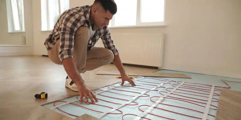
The manifold is the central distribution point for underfloor heating. The water travels from the primary household heating source (e.g. gas boiler), where the water is cooled to the specified UFH temperature and pumped under the floor surface. It travels under each area, transferring its heat up through the floor, before arriving back at the manifold and travelling back to the boiler for reheating. Being the central point of the system, you must assemble and mount the manifold first.
Position
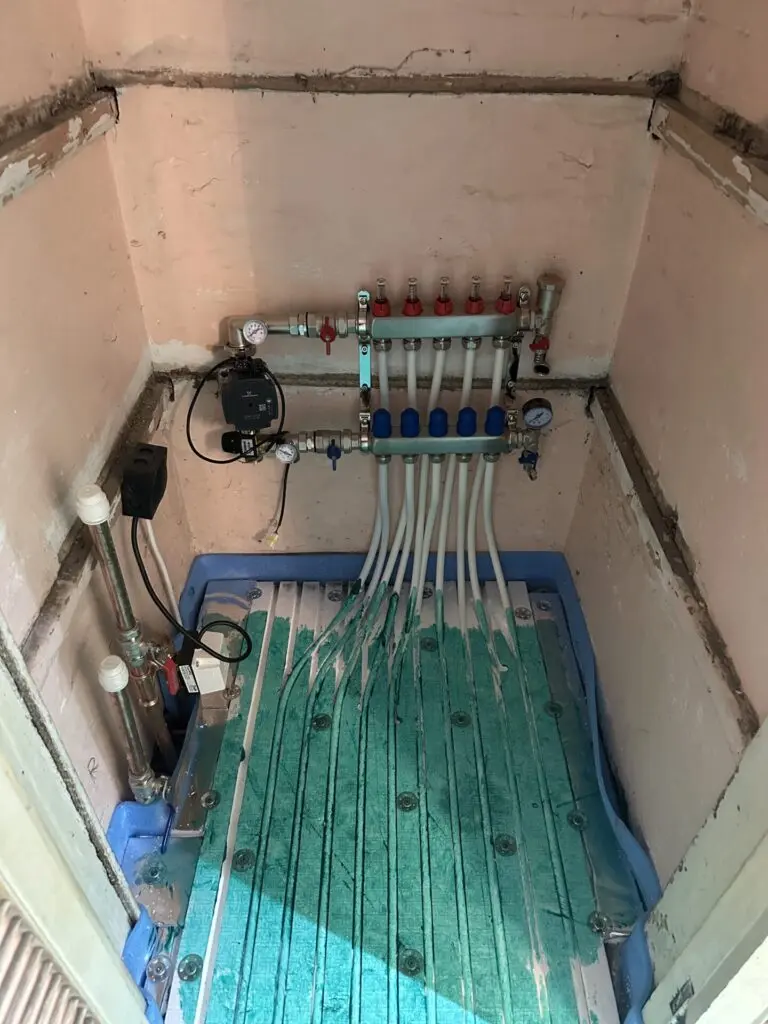
The manifold installation position should be centrally located in the property such that distribution to each heated area is efficient and involves minimal long pipe runs. Ensure that copper pipework to and from the boiler can reach the designated manifold location. If you are unsure about manifold position, our vps team are on hand to provide assistance. The installer should allow for the following recommended clearances when mounting the manifold on the wall: Recommended minimum installation clearances:
- 200 mm between finished floor level and the bottom of the manifold
- 100 mm above the manifold
- 50 mm either side of the manifold
Assembly
Your manifold can be assembled in various configurations, chosen based on the geometry of the manifold location, and which configuration will be able to meet the installation clearances. Both configurations along with dimensions of all sizes of manifolds are viewable on our manifold home page.
- At your chosen/designated manifold location, mount the manifold on the wall using strong fittings/raw plugs, at the specified installation clearances.
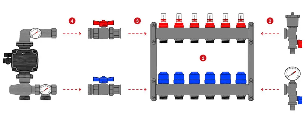
- Insert the Auto Air Vent assembly and pressure gauge assembly, shown below, ensuring they are tight.
- Connect ball valves to the other end of the manifold.
- Connect and tighten the manifold control pack (where applicable). Ensure that the pump and blending valve are both in the correct orientation, as denoted by arrow markings on each unit.
Connecting pipe
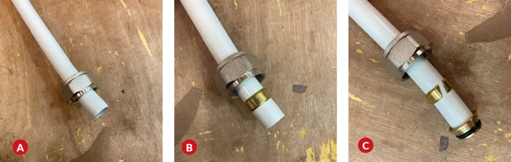
Once rounded, A. slide the 16 mm Eurocode nut over the end of the pipe (A), before fitting the split compression olive to the pipe (B) and inserting the push fitting(C). Ensure the push fitting fits in the end of the pipe before proceeding to connect to the manifold. Attach the assembled pipe end to the relating port, torquing the nut to approx. 50 Nm or one-and-a-half spanner turns after hand tightening.
Connecting to a central heating source
connecting to the central heating source is the main step of installing an underfloor heating manifold. The underfloor heating manifold functions as a distribution node for the hot water provided by your household heating source. It takes the hot flow, and blends it with the return flow such that the temperature is correct before sending a flow to each heated area under the floor.
If the hot supply is the correct temperature before reaching the manifold (i.e. from a heat pump or a single-purpose boiler) then the pump and blending valve is not required. The heating source is then connected to the manifold.
Please note that VPS will not conduct design works of the hot inlet pipework; a qualified plumber or confident DIYer should conduct this
Filling, venting and pressure testing
1. Close the red and blue ball valves connected to the pump, as well as the blending valve (where applicable). Valves must be closed to ensure water remains in the manifold.
2. Remove the end caps from the fill and drain valves and connect the ½” hose unions supplied.
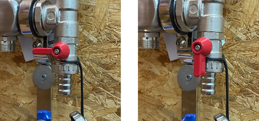
3. Open the small red and blue ball valves connected to the fill and drain points.
Valve on air vent assembly in the closed position. Valve on air vent assembly in the open position.
4. Connect a suitable hose from the mains water supply to the hose union on the flow bar (red), and connect another hose from the return bar (blue) to a suitable water collection point, eg. A bucket.
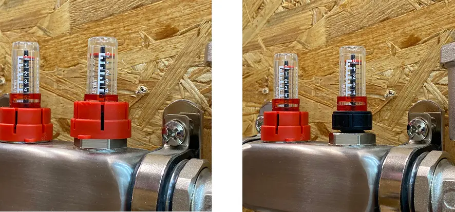
5. Close all flow ports by removing the red cap and twisting them clockwise until they stop. Close the return ports by twisting the blue head clockwise.
Flow valve, shown with the locking cap attached. Once removed, the black part can be twisted.
6. Fill each loop by opening the first set of flow and return ports by twisting them anti-clockwise.
7. Turn on the mains water supply to begin filling the first loop. Observe the relevant flow meter; the indicator should move to the bottom of the viewing glass.
8. Watch the return flow from the hose; when it stops ‘spitting’ and begins to flow smoothly, the air has been purged from the loop. Another way to verify this is by submerging the end of the hose in a bucket of water and waiting until air bubbles cease to appear.
9. Close the flow and return valves on the first loop and open the flow and return ports on the second loop, before repeating the filling process from steps 6-8. Repeat this for all loops on the manifold.
10. When filled and vented, open all flow and return ports.
11. Close the blue drain valve on the right-hand side of the manifold and disconnect the hose, before removing the hose union and reinstalling the end cap.
12. Connect a pressure pump to the hose union on the flow bar. Open the red ball valve on the vent and close the blue ball valve on the drain.
13. Increase the system pressure up to a maximum of 6 bar. The pipes will expand, causing a slight pressure drop which will level out and cease to decrease any further. Monitor the pressure gauge to ensure constant pressure.
14. Once the gauge reading has settled, begin to decrease the system pressure to the specified working pressure. Once this value is reached, the pipe swelling from the high pressure will subside, and the tightening pipes will increase the system pressure slightly. Wait until this stabilises, and then leave the system at working pressure for an hour. If there are any leaks, the pressure will decrease during this time. If the pressure has not decreased, the system is tight and leak-free.
15. Ensure the system remains under pressure as the floor is being laid to prevent any compression of the pipes and ensure immediate detection of damage or leaks.
Get in contact
We hope our underfloor heating manifold installation guide has provided valuable insights into the steps which are required. Should you have any further questions or need assistance with manifold installation or any part of your UFH project, our team of experts is here to help. Our premium manifolds are designed to meet your specific needs, browse through our selection of manifolds and discover the ideal fit for your project.