Manifolds & Actuators


What is an underfloor heating manifold?
An underfloor heating manifold serves as the heart of a wet underfloor heating system. Managing the distribution of heated water from the heat source to different zones. The manifold can provide precise control over multiple zones by regulating the flow through separate pipes. A manifold permits uniform and optimal heating conditions across the entire home.
Components of an underfloor heating manifold
- Flow Meter – Measures the flow rate of water passing through each loop. One is required for each port.
- Flow Manifold Rail – The flow rail houses all flow ports and flow meters.
- Return Manifold Rail – Holds all return ports and flow caps.
- Flow Pipe Connection Port – One end of the pipes connects to these ports. water flows from the underfloor heating manifold into the pipes from here.
- Return Pipe Connection Port – The other end of the pipes connects back to these ports. Water passes back into the system from here.
- Flow Ball Valve – Provide a shut-off mechanism in the flow
- Return Ball Valve – Provides a shut-off mechanism in the return
- Air Vent– Releases trapped air within the system.
- Fill Port– Provides port to fill the system with water using a hose.
- Pressure Gauge – This allows you to monitor pressure within the manifold.
- Drain Port – Provides a port to drain the system using a hose.

How does a heating manifold work?
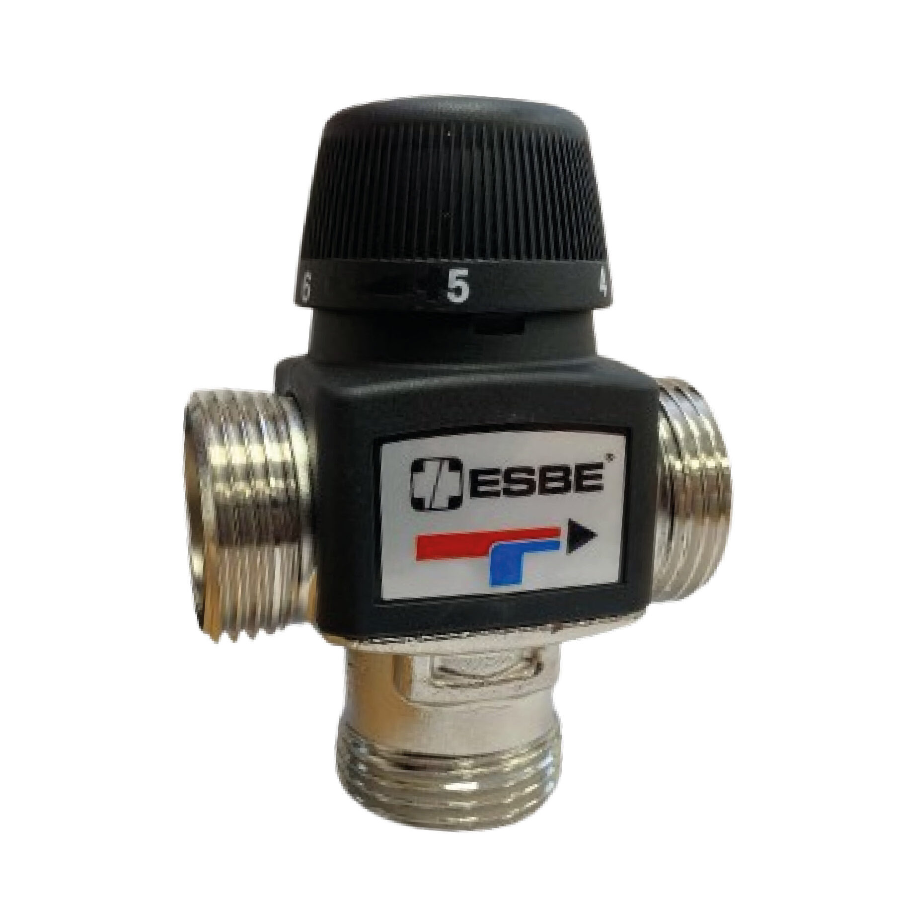
The manifold plays a crucial role in distributing heated water to the relevant zones. The diagram below displays the relationship between various components in your underfloor heating system. Heated water passes into the system from the heat source, through the blending valve and pump. The heated water flows to the relevant zones which require heat.
Underfloor heating manifold diagram

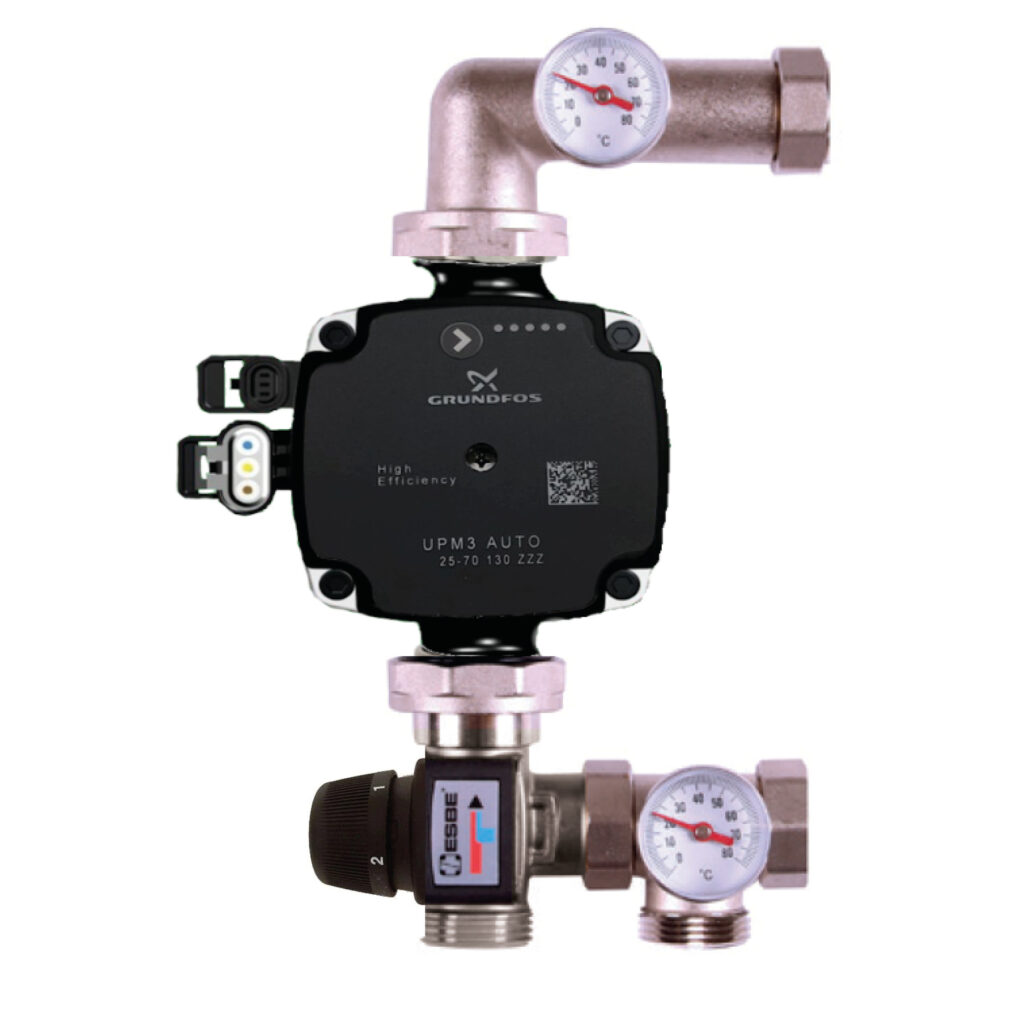
Pump/Control Pack
The pump circulates heated water around the system. Using an efficient pump maintains the correct flow rate of water through the system. Our manifold control pack includes a pump, blending valve, and the correct fixtures to connect straight to the manifold.

Underfloor heating manifold dimensions
Below are the dimensions of our underfloor heating manifold and control pack. The installer should allow for the following recommended clearances when mounting the manifold on the wall: 200 mm between the finished floor level and the bottom of the manifold. 100 mm above the manifold. 50 mm on either side of the manifold.


Layout 1 is the standard setup for a manifold. Ball valves are placed between the manifold and the pump. This allows servicing or maintenance without draining the entire system.
| Port | 2 | 3 | 4 | 5 | 6 | 7 | 8 | 9 | 10 | 11 | 12 |
|---|---|---|---|---|---|---|---|---|---|---|---|
| A | 189 | 239 | 289 | 339 | 389 | 439 | 489 | 539 | 589 | 639 | 689 |
| B | 273 | 323 | 373 | 423 | 473 | 523 | 573 | 623 | 673 | 723 | 773 |
| C | 465 | 515 | 565 | 615 | 665 | 715 | 765 | 815 | 865 | 915 | 965 |
A – Width of manifold including fill & drain ports
B – Width of manifold & ball valves
C – Width of manifold, ball valves & pump

Layout 2 is preferred when horizontal space is limited. Installing the ball valves below the pump allows the length to be decreased. Shut-off valves are still included in the system.
| Port | 2 | 3 | 4 | 5 | 6 | 7 | 8 | 9 | 10 | 11 | 12 |
|---|---|---|---|---|---|---|---|---|---|---|---|
| A | 189 | 239 | 289 | 339 | 389 | 439 | 489 | 539 | 589 | 639 | 689 |
| B | 365 | 415 | 465 | 515 | 565 | 615 | 665 | 715 | 765 | 815 | 865 |
A – Width of manifold including fill & drain ports
B – Width of manifold & ball valves
Installing UFH manifolds
This quick guide outlines key steps for installing an underfloor heating manifold. Visit our installation blog post for further details.
Troubleshooting your manifold
Below is a quick guide for identifying problems with your underfloor heating manifolds.
- Power Supply: The thermostats and wiring centre are the powered components of the system. Ensure both receive power and are working correctly. The pump and actuator are powered through the wiring centre. Ensure there is no interruption in the power supply.
- Thermostat: Verify that the thermostats are set to the desired temperature. The thermostats will indicate when they are signalling for heat. Check the related actuator to see if the valve is open.
- Valve: Ensure valves are not stuck or blocked. Valves can get jammed due to debris or sediment build-up.
- Pressure: Check the pressure flow meters on the manifold. Ensure system pressure in all loops is within the recommended 1 and 2 bars. other measurements could indicate problems in the system.
- Balancing: Uneven heating or colder spots in certain areas could indicate imbalances in the system or incorrect zoning settings.
- Temperature: Check the temperature difference in the flow and return rails. Indicated on the 2 dials on our standard control pack. The temperature drop should be around 5-10 °C. If the value is out with this range, the circulation pump or flow rates may be the cause.
- Call VPS: If you’re uncertain about the problem, give us a call. We will do our best to identify any issues in the system.
What is an underfloor heating actuator
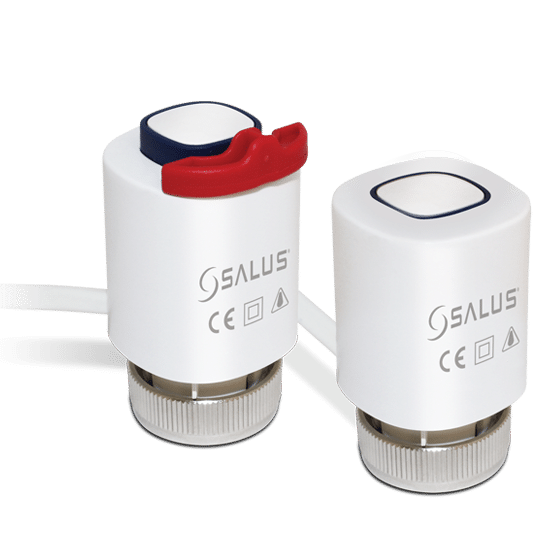
An underfloor heating actuator (thermal actuator) provides automatic control of the flow of water through each loop. The actuator is connected to the return port and opens or closes the valve according to signals sent by your wet underfloor heating thermostat. Actuators are normally wired to an underfloor heating wiring centre, which acts as the central hub for the electrical signals.
How long do underfloor heating actuators last
230v UFH actuators can last over 10 years, depending on use. Manufacturer warranties typically cover them for 2 years (Heatmiser) or 5 years (Salus).
Are underfloor heating actuators open or closed?
Actuators do both – this is their primary function. When the system requires heat, the actuator opens the valve. When the system is off, the actuator closes, stopping the flow of water through the loop. Since actuators are fitted per loop, each loop on the manifold is controlled independently.
Fitting UFH actuators
Below are the steps to connect your actuator to a VPS manifold. Exact connections may vary depending on the model:
- Remove the blue flow cap to expose the actuator valve on the return port.
- The actuator comes with a threaded ring nut attached to the bottom. Place the unit onto the valve and screw the ring nut onto the valve thread.
- Connect the wiring from the actuator to the appropriate control source. This is usually a wiring centre, which also powers the unit.
- After completing the installation, remove the red tab that holds the control unit open (Salus). Perform a system test to ensure the actuator responds correctly to control signals.
Useful Links
About Us
Free UFH Quote
Delivery & Returns
Trade Customers
Product Guidance
Knowledge Hub
UFH Blogs
Manuals & Guides
FAQ’S
© 2026 VPS Trading Ltd – Registered in Scotland – SC604192 – VAT No. GB303867306